EN 1665 does not contain a tightening torque. The standard fixes what a heavy-series hexagon flange bolt must measure and what strength class it may be supplied in from M5 to M20; it does not say how far the bolt should be stretched when installed, and that stretch — the clamp force — is the only thing a torque value exists to produce.
A torque figure labelled “DIN EN 1665” is therefore either a calculation with unstated assumptions or a number carried across from a different joint. Neither is a requirement of the standard. Determining the right value means fixing five inputs in order: the clamp force the joint needs, the geometry and strength of the bolt, the friction in the thread, the friction and bearing diameter under the flange, and the accuracy of the tightening method. The rest is arithmetic.
The standard fixes the bolt, not the joint
EN 1665:1997 is the European product standard for hexagon bolts with flange, heavy series. It was published in Germany as DIN EN 1665:1998-11 and corrected in 2007, and its scope is M5 to M20 in property classes 8.8, 10.9 and A2-70. Fine pitches and class 12.9 are outside it, so a “12.9 EN 1665” bolt is a special part to drawing rather than a standard product. How the EN 1665 head relates to the older DIN 6921 head and to the small-series ISO 4162 is covered in our comparison of the three flange bolt standards; for torque, the differences that matter are the thread and the flange face.
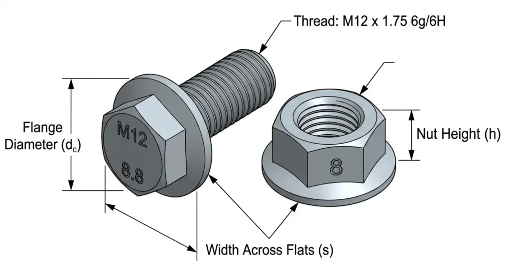
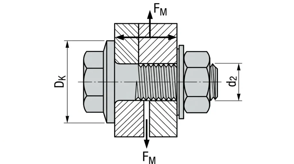
Three dimensions from the standard feed the calculation directly. Nominal diameter and pitch set the thread geometry: the pitch diameter d2, where thread friction acts, and the stress area As, which converts a strength into a clamp force. The flange bearing face sets the diameter at which friction acts under the rotating head. That last one is why a flange bolt cannot simply inherit a torque written for a plain hexagon bolt: the bearing term is proportional to the mean bearing diameter, and an EN 1665 flange presents a wider face than the washer face of a hexagon head on the same thread. Use the smaller diameter and the calculated torque comes out low for the clamp force wanted.
The dimension and property-class records are public: the German edition is catalogued as DIN EN 1665:1998-11, and the classes the standard lists are the strength labels a buyer orders against. What none of that establishes is how much of the bolt’s strength a particular joint is allowed to use.
Clamp force is the requirement; torque is only the control
A bolted joint works because the bolt is stretched and the clamped parts are compressed. The joint needs a minimum clamp force — enough to keep a gasket seated, enough friction to carry a shear load, enough residual tension that the joint does not open under service load, or enough preload to keep a fatigue-loaded bolt below its endurance limit. That number belongs to the joint. It comes from a joint calculation such as VDI 2230, from a flange-joint assembly procedure such as ASME PCC-1, or from the equipment manufacturer’s specification. It does not come from the bolt standard, which has no view of what the bolt is clamping.
Torque is one way to reach that force, and it is indirect. Most of the torque applied to an EN 1665 bolt is consumed by friction in the thread and under the flange; only a small share becomes clamp force. At the friction levels used in the worked example below, that share runs from 6% to 16% depending on lubrication. Change the lubricant, the coating or the surface finish and the clamp force at the same torque changes with it — for one M10 bolt, the same 49 N·m produces about 24 kN at μ = 0.14 and about 12 kN in a dry assembly at μ = 0.30.
That is why a torque value is better read as an inference than as a measurement, the same distinction that separates torque tightening from direct tension indication in structural bolting (DTI washers versus torque tightening). The inference is only as good as the friction assumption behind it.
The five inputs behind any flange-bolt torque value
- Required clamp force. From the joint design or the equipment specification: gasket seating, shear capacity, residual tension, fatigue limit. Not from the bolt standard.
- Bolt geometry and strength. Nominal diameter, pitch, stress area and property class, from EN 1665 and ISO 898-1. Class 8.8 sets a 640 MPa minimum yield at M10, class 10.9 sets 940 MPa, and A2-70 stainless sets a 450 MPa 0.2% proof strength. For M10 × 1.5 the stress area is 58.0 mm².
- Thread friction. The coefficient μG in the actual thread, measured on the actual bolt, nut or tapped hole, coating and lubricant, or taken from the joint designer’s calculation.
- Bearing friction and bearing diameter. The coefficient μK under the rotating face, and the mean bearing diameter DK derived from the EN 1665 flange face and the clearance hole.
- Tightening method and its scatter. Hand torque wrench, powered tool, torque-and-angle, or tensioner; how well the tool is calibrated; whether the result is audited on the line.
Each input has an owner. The joint designer owns the first, the bolt standard and the supplier own the second, the coating and lubricant specification plus a torque/clamp-force test own the third and fourth, and the assembly process owns the fifth. A generic torque table gives the second and quietly assumes the rest, which is why two joints with the same bolt can legitimately need very different torque values.
From clamp force to torque
The standard engineering form is the tightening-torque equation of VDI 2230 Part 1, which splits the torque into the three things it does:
MA = FM [ P / (2π) + μG d2 / (2 cos 30°) + μK DK / 2 ]
- MA is the tightening torque, FM the preload or clamp force it should produce.
- P / (2π) is the useful part: the work of advancing the thread through one pitch. At M10 × 1.5 it contributes 0.24 mm of the 2.04 mm total.
- μG d2 / (2 cos 30°) is thread friction, with d2 the pitch diameter and the 30° coming from the 60° ISO metric thread form.
- μK DK / 2 is bearing friction under the head — for a flange bolt, under the flange face.
Collapsing the bracket into a single coefficient gives the form used in most handbooks, MA = K FM d, with K between roughly 0.10 and 0.30 for common steel fasteners. K is convenient and easy to misuse, because it absorbs the bearing diameter. A K taken from a plain hexagon bolt table carries a smaller DK than an EN 1665 flange does, so the flange bolt comes out under-torqued for the same assumed friction.
Because the achieved clamp force scatters around the calculated value, the torque in a specification is normally set so that the minimum clamp force still satisfies the joint, not so that the average does. VDI 2230 carries that margin through a tightening factor that depends on the tool and on how well friction is controlled.
Worked example: M10 × 1.5, class 8.8, oiled
- Stress area. For M10 × 1.5, d2 = 9.026 mm and d3 = 8.160 mm, so As = π/4 × 8.593² = 58.0 mm².
- Strength limits. Class 8.8 gives a 640 MPa minimum yield and a 580 MPa proof-load stress, so the proof load is 580 × 58.0 ≈ 33.6 kN. A preload above that leaves the bolt permanently stretched, whatever the friction.
- Preload. The first estimate is 70% of yield, 26 kN, but it has to survive the stress the bolt carries while it is being tightened. The shank sees tension and torsion together, and VDI 2230 compares the equivalent stress σred = √(σ² + 3τ²) with a permitted fraction of yield — commonly 90%. At 26 kN and μG = 0.14 the two components are σ ≈ 448 MPa and τ ≈ 236 MPa, giving σred ≈ 607 MPa, or 95% of yield. At μG = 0.30 the same preload would need about 107 N·m and σred would pass 880 MPa, so a dry joint cannot be pulled to 26 kN at all. On the conservative minor-diameter reading used here, the permissible assembly preload at μ = 0.14 is about 24.7 kN.
- Bearing diameter. The EN 1665 M10 flange has a 19.6 mm bearing face; with an 11 mm clearance hole, DK = (19.6 + 11) / 2 = 15.3 mm.
- Friction. Take μG = μK = 0.14 for a lightly oiled assembly, as it would be measured on production parts.
- Torque. With a required preload of 22 kN, below the 24.7 kN limit, the bracket is 0.239 + 0.730 + 1.071 ≈ 2.04 mm; multiplied by 22,000 N that is 44,900 N·mm, or about 45 N·m, with K = 0.20. At 22 kN, σred ≈ 513 MPa — 80% of yield — and the proof load is not approached.
| Friction μG = μK | Permissible assembly preload | Torque to reach it | σred |
|---|---|---|---|
| 0.10 — well lubricated | 27.2 kN | 41 N·m | 576 MPa |
| 0.14 — lightly oiled | 24.7 kN | 50 N·m | 576 MPa |
| 0.20 — dry, zinc plated | 21.3 kN | 60 N·m | 576 MPa |
| 0.30 — dry, unlubricated | 17.0 kN | 70 N·m | 576 MPa |
The rows are not interchangeable. The 50 N·m that suits μ = 0.14 takes an assembly at μ = 0.10 to σred ≈ 695 MPa — past yield, so the clamp force never settles at the 33 kN the arithmetic suggests — and leaves a dry assembly at μ = 0.30 with about 12 kN. A torque value without its friction condition is not a specification.
The same check at other classes: class 10.9 allows about 36.3 kN at μ = 0.14, or about 74 N·m, if the nut, the flange and the clamped material accept it; A2-70 stainless allows about 17.4 kN and 35 N·m. Both are permissible assembly preloads from the stress check, not invitations to use the full strength of the bolt, and stainless still needs a lubricant to control galling, which changes the friction again.
Where the friction numbers should come from
ISO 16047:2005, still the current edition with its 2012 amendment, is the test standard for this. It defines how a torque/clamp-force test is run on production fasteners and how the resulting thread and bearing friction coefficients are reported. Running it on the actual combination — this bolt, this coating, this lubricant, this nut or tapped hole, this flange face, this hole size — is what turns an assumed μ into a measured one.
The test conditions have to match the assembly or the result describes a different product. Coating and lubricant are the obvious variables. Less obvious are the mating thread (nut class, tapped-hole material, thread engagement), the bearing surface (plain flange, flange nut, washer, clamped material), the tightening speed, and whether the parts are new or reused. A value measured on a zinc-plated bolt with a wax film does not describe a hot-dip galvanized bolt, whose thicker coating changes both thread fit and friction; it does not describe a stainless bolt either, which galls unless it is lubricated.
Without a test, the second-best source is the joint designer’s stated friction assumption, carried with the calculation. The weakest source is a number copied from another product’s catalogue.
Points specific to flange bolts
The flange is the feature that makes these bolts useful: it turns the head into a washer-sized bearing surface, as described in what hex flange bolts are and where they help. It is also the feature that most often gets a torque calculation wrong.
- Bearing diameter comes from the flange, not from a hexagon washer face. Read the bearing face diameter from the EN 1665 table for the size, then pair it with the actual hole. Oversize or slotted holes raise DK but also let the flange embed.
- A flange nut adds a second bearing face. The torque then has to satisfy two friction surfaces, and the nut’s property class must match the bolt’s or the nut thread strips before the bolt reaches preload.
- Surface pressure can cap the preload. The flange spreads the load, but on aluminium, cast iron, thin sheet or plastic the allowable bearing pressure may be reached well below 70% of the bolt’s yield. The answer there is less clamp force and less torque, not more.
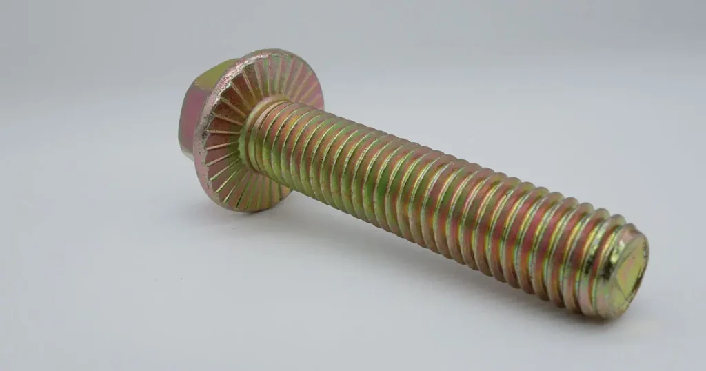
- A serrated or toothed face is a different friction condition. A μ measured on a plain flange does not transfer to it, and the teeth mark the clamped surface.
- Coating changes both friction and fit. Electroplated zinc, zinc flake with integral lubricant, hot-dip galvanized and plain oiled parts each need their own tested values; hot-dip galvanizing also needs its thread allowance.
- Stainless A2-70 is not a steel bolt with a different label. Lower proof strength, galling risk and a lubricant requirement that changes friction mean it needs its own torque, not the 8.8 figure.
- Prevailing-torque features consume torque without adding clamp force. A nylon insert, a patch or a distorted thread adds friction that the torque wrench sees, and reuse changes it again.
When to test instead of calculate
Calculation is adequate for a joint with known friction, moderate criticality and a torque audit. Testing or direct measurement is the better route when the finish or lubricant is new or has changed, when the joint is safety-critical or pressure-retaining, when a gasket, fatigue load or dissimilar materials are involved, or when the first production run has to prove the process.
Beyond a torque wrench, the options are torque-and-angle tightening to a defined rotation past snug, hydraulic tensioning, ultrasonic bolt elongation, load-indicating washers, and instrumented tightening that measures clamp force directly. Each controls something closer to clamp force than torque does, at a cost in tooling and time. On a flanged joint the tightening pattern and the number of passes also change the result, which is why flange-joint procedures specify the sequence as well as the torque — ASME PCC-1 sets out that assembly procedure for pressure-boundary flange joints.
Why a published EN 1665 torque chart is not a specification
Charts are popular because they produce a number without the work, and three things are usually missing from them. The friction assumption is the first: a torque with no stated coating and lubricant describes no particular assembly. The bearing diameter is the second: a table built for plain hexagon bolts, or for a different flange standard, applies the wrong bearing term to an EN 1665 flange. The joint is the third: one bolt may need twice the clamp force in a pressure joint and half of it in a bracket, and the chart cannot know which.
Equipment manufacturers’ tightening instructions are a different case, and a more useful one. A pump or valve manual that gives a torque for its flange is specifying that assembly — its gasket, its bolt size, its grade, its lubricant. That figure is the maker’s requirement for that equipment and should be followed as such. It is not a DIN EN 1665 torque value, and merging values from several manuals into a general flange-bolt chart produces a table that is right for none of them.
What to write on the drawing, the order and the work instruction
A usable specification carries the friction assumption and the verification method alongside the number. For the example above it would read:
- Bolt: M10 × 35, EN 1665, class 8.8, zinc flake coating with integral lubricant.
- Friction: μG = μK = 0.14, from an ISO 16047 test on production parts, test report attached.
- Preload: 22 kN at μ = 0.14, per the joint calculation.
- Torque: 45 N·m ±10%, calibrated wrench, sequence as shown on the assembly drawing.
- Verification: torque audit on 10% of joints; any joint disturbed after tightening to be re-tightened and re-audited.
The ±10% is doing real work. At 49.5 N·m a joint at μ = 0.14 reaches about 24 kN, with σred ≈ 566 MPa or 88% of yield; if friction falls to 0.12 the same torque gives about 28 kN and σred ≈ 618 MPa, or 96%. At 40.5 N·m in a joint that has drifted to μ = 0.16 the clamp force falls to about 18 kN. That spread is why the torque above is a calculation result for a stated friction, not a production specification: the friction band, the wrench and the scatter together decide whether torque control can hold the joint, and where they cannot, preload has to be controlled directly.
For a buyer, the split of responsibility is worth stating plainly. A bolt supplier can certify dimensions, property class, coating and marking, and can run a torque/clamp-force test on request; the supplier cannot decide the joint’s clamp force. An enquiry that says only “M10 EN 1665 8.8” will produce a correct bolt and no defensible torque. An enquiry that also states the finish and the lubricant gives both sides something to calculate from.
ChinaBolts supplies DIN 6921 and DIN EN 1665 hexagon flange bolts from M5 to M20 in classes 8.8, 10.9 and A2-70, part of the wider bolts range. Where the joint needs a defined friction condition, put the coating and lubricant on the enquiry so the torque follows from the assembly rather than from a chart.
The tightening torque for an EN 1665 flange bolt is not in EN 1665. It falls out of five inputs: the clamp force the joint needs, the bolt’s geometry and strength, the thread friction, the bearing friction and diameter under the flange, and the accuracy of the tightening method. Four of those live outside the standard. Supply them and the arithmetic above is all there is; leave them out and any number — including one from a table headed “DIN EN 1665” — is a guess with a decimal point.