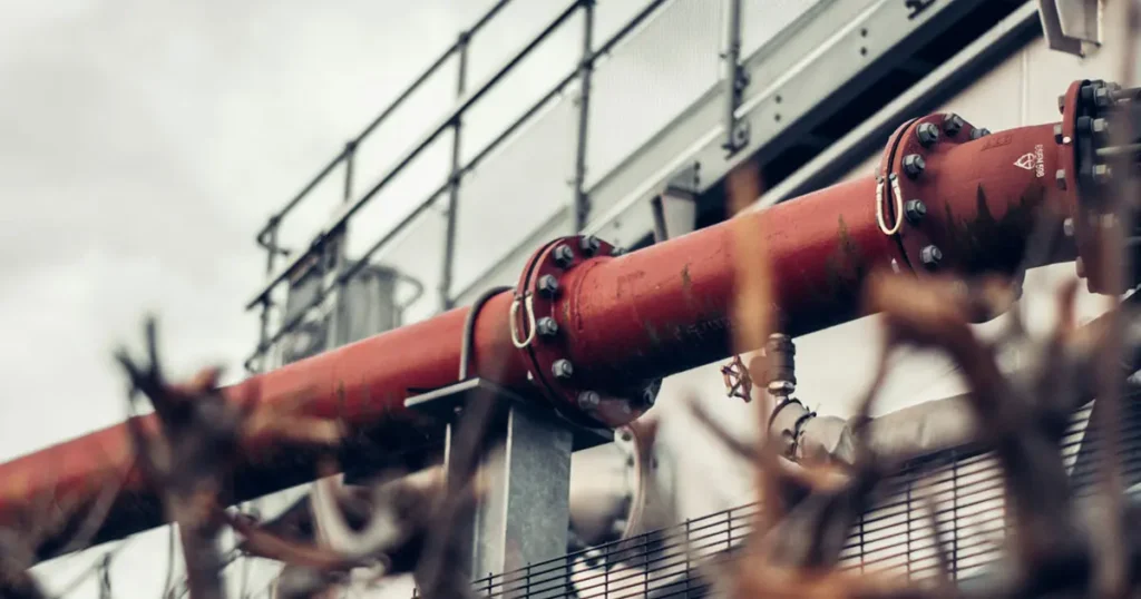
A U-bolt is used to clamp a round or shaped component against a support, bracket or plate. It is a bolt bent into a U, with a thread rolled onto both legs, so the bend wraps around the part being held while the two straight legs pass through holes in the support and are drawn down with nuts. That single geometry covers most of what U-bolts do in practice: holding pipe and tube onto supports, fixing round and square sections and equipment feet to structures, and clamping components into brackets. What changes between applications is not the bolt but the job being asked of it — holding a part in place, limiting its movement, or allowing movement in one direction while blocking it in another. Those three jobs lead to different tightening, different accessories and, sometimes, a different product.
What a U-bolt is and how it works
Structurally, a U-bolt belongs to the family of bent bolts. ASME B18.31.5, Bent Bolts (Inch Series), groups U-bolts with eyebolts, hook bolts and J-bolts, and its dimensional tables cover U-bolts of differing bends. The defining feature of the U-bolt within that family is the two threaded legs: the thread is what turns a bent bar into a fastener, because it is the only part of the bolt that can be tightened.
Mechanically, the bolt works as a clamp rather than as a pin or a stud. The inside of the bend sits against the component; the legs pass through the support; the nuts pull the bend down onto the component. The force the assembly develops is therefore a clamping force at the surface of the clamped part, and it depends on how far the nuts are tightened, on the thread and on the contact between the bend, the part and the support. The bend also determines how the load reaches the part: a round bend matches the outside diameter of a pipe or tube and spreads contact around it, while a square bend presents straight legs and a flat back better suited to a flat mounting face.
The three jobs a U-bolt does in an assembly
Most application questions come down to one of three functions, and the distinction matters because it decides how the bolt is set, how much of the assembly is U-bolt and how much is something else.
| Job | What the U-bolt does | What it means in practice |
|---|---|---|
| Securing | Holds a component against a support or bracket so it cannot lift or separate | Nuts tightened so the component is held firmly to the support; this is the most common use, and the one most U-bolts are bought for |
| Restraining | Limits movement of the component — for pipework, the thermal movement that a changing temperature produces | The bolted joint is part of a restraint, so how tight the nuts are set and what the bend bears on both become part of the support design |
| Guiding | Allows movement in one direction while blocking it in another | The joint has to permit sliding along the component, which means controlling contact and clearance rather than simply tightening down |
The third row is where U-bolts are most often misapplied. In piping, the difference between a restraint and a guide is a design decision, not a preference: a guide allows axial movement of the pipeline but restricts lateral movement, while a restraint limits thermal movement and a support carries the weight. That distinction follows from the way piping codes treat expansion — ASME B31.3 observes that a piping system changes dimension with every temperature change, and that guides and anchors are among the restraints that displace it from its free position. A U-bolt tightened hard onto a pipe acts as a restraint at that point. Where the line is meant to slide, the assembly has to allow it — through a liner, a controlled clearance or a different attachment — and a bolt tightened down as though the pipe were a static bracket defeats the design.
Common applications
Pipe and tube support
This is the application U-bolts are most closely associated with, and the one with its own standard. DIN 3570 is titled as a round-bar U-bolt for pipes and covers nominal widths from 20 to 500. Its dimensions are keyed to the pipe the bolt clamps rather than to the thread: in the standard’s table, the U-bolt size is the inside width between the legs and each size is assigned the pipe outside diameters it suits.
A representative row shows how the two relate: size 46, for example, is tabulated for pipe of 38 to 42.4 mm outside diameter with an M10 thread on both legs, a 50 mm minimum thread length on each leg, a 56 mm distance between leg centres and an 86 mm overall height. Two consequences follow for anyone specifying these bolts for pipework. The input is the measured pipe outside diameter, not the nominal pipe size, and the thread has to be read off the standard’s table because the size number does not encode it: inside width grows from 30 mm to 530 mm across the range while the thread steps through M10, M12, M16, M20 and M24.
DIN 3570 U-bolts are supplied in two forms: Form A with two equal threaded legs, and Form B with one long threaded leg and one shortened plain leg for positions where access allows tightening from one side only. DIN 3570 itself specifies the bare bolt; nuts and washers are separate items.
Outside the pipe-clamp standard, the same geometry is used to fix tube, conduit and cable to strut, channel, angle and bracketry, and to hold pipe runs during transport and storage so that they cannot move against each other. Where the line is insulated, coated or made of a soft material, the contact between the bend and the component is usually what limits the arrangement rather than the bolt.
Equipment and component mounting
A second large group of uses has nothing to do with pipe. Any round or square section, tube or foot that has to be held against a flat surface can be clamped with a U-bolt, which is why the part appears on vehicle axles and suspension, on exhaust and intake tubing, on trailer and chassis frames, on marine deck and rigging fittings, and on general machinery where a bracket holds a shaft, cylinder or actuator in position. Square-bend U-bolts are the usual choice here, because the flat back of the bend suits a flat mounting face and the straight legs pass through a plate or flange.
The engineering question in these applications is the same as in pipework: what the bolt has to prevent. A U-bolt is good at holding a component down. It is poor at resisting rotation of a round component about its own axis, and it provides no positive location along the axis of the clamped section unless something else — a shoulder, a welded stop or a bracket wall — does that job. Vibration is the other practical factor: a clamped joint that loosens under vibration loses its clamping force before it loses its position, which is why a U-bolt used on dynamic equipment is normally checked and re-tightened rather than assumed to stay put.
Structural and general fastening
U-bolts are also used to attach fittings, poles, posts, rails and attachments to structures, to fix components to concrete through cast-in or anchored plates, and to clamp two sections together where a through-bolt is not possible and a clamp is. In these roles they behave as general mechanical fasteners rather than as part of a piping system, and they are selected on the same basis as any other clamped joint: the size of the parts being held, the thread needed to develop the clamping force, and the material and finish that suit the environment.
A closer look at the assembly
A U-bolt on its own does not hold anything. The bolt is one item in an assembly, and the other items decide whether the joint behaves as intended.
- The U-bolt body. The bent bar is the part that carries the load around the component. Its inside width sets what it can clamp, its bar diameter sets how much of the leg is available to be threaded, and its bend form sets what it can sit against.
- Nuts. One or two per leg, in the thread the legs carry. The nuts are what develop the clamping force, and they are also the part that can be lost, cross-threaded or left loose. Two nuts per leg are used where a locked position or a greater bearing area on the support is wanted. A DIN 934 hexagon nut is the ordinary metric match for a metric-threaded U-bolt leg; where the legs are inch-threaded, the matching inch nut is required. A leg that carries no thread — the short leg of a single-sided U-bolt — takes no nut at all.
- Washers. A washer under the nut spreads the clamp load over a larger area of the support and protects the surface it bears on. The support is usually the weakest link in the joint, a thin channel web or a slotted bracket can deform locally as the nuts are tightened, and the washer is what stands between normal tightening and that damage.
- Mounting plate, saddle or bracket. Many U-bolt assemblies clamp against a plate rather than against a bare structural face, and the plate is what carries the load into the structure. Where the plate has a shaped seat for the pipe, the pipe is supported over an area rather than along a single line of contact, which is why the plate, and not the bolt, usually determines how much clamping force the joint can usefully use.
- Liner or protective coating. A liner is a separate item that sits between the bend and the component. It protects the surface of the clamped part and, where the component is meant to slide, provides a low-friction interface so the pipe can move. For pipework carrying a hot or cold medium, that last point can be the whole reason the liner is specified. A liner is not part of the U-bolt, and a change in liner thickness changes the inside width required, so it belongs in the specification and not in a separate conversation after the order.
The forms a U-bolt is made in
The bend is the first thing to look at when identifying a U-bolt, because it decides what the bolt can sit against. Three bend configurations cover most of what is bought and sold.
- Round bend. The bend is a semicircle matched to the outside diameter of the pipe or tube it clamps. This is the form used for pipe support, and it is the form DIN 3570 specifies.
- Square bend. The bend is formed with two corners and a flat back, so the bolt presents straight legs and a flat bearing face for a plate, flange or channel.
- Long tangent or extended-leg U-bolt. The straight portion of each leg is longer than the bend itself, for supports deeper than the standard form reaches.
- Single-sided U-bolt (one shortened plain leg). Still a U-bolt: one leg carries the thread and the other is shortened and left plain, for positions where the bolt has to be inserted and tightened from one side only. In DIN 3570 this is Form B, and it is specified over a smaller size range than the two-leg form.
A J-bolt is a different bent fastener, not a form of U-bolt: it has a single threaded leg, so it hooks or anchors rather than straddling the component with two legs. It is the part to consider when the fastening need is genuinely one-sided and no second leg can be accommodated, and it belongs in a specification as its own product type.
Two related parts are frequently confused with the U-bolt and are worth separating. A two-part pipe clamp is a different product, made from two shaped halves bolted together; and a U-bolt strap or clamp assembly is a U-bolt supplied with a shaped counter-plate. Neither is a U-bolt in the sense used here, and the standard number in a specification line is the quickest way to tell them apart.
Reading a U-bolt description
Because the size of a U-bolt is defined by a shape rather than by a single diameter, a U-bolt description has to carry the dimensions that the designations leave out. Four of them are needed before the part can be identified at all.
- Inside width: the distance between the inside faces of the two legs. This is the dimension that has to clear the component, plus any liner or coating. On a pipe U-bolt it is the size number itself.
- Thread: the thread size and pitch on the legs. It is not the same as the bar diameter, and it is not implied by the inside width. Where a standard applies, the thread for each size comes from the standard’s table.
- Leg length and thread length: how far each leg reaches and how much of it is threaded. On a standardised U-bolt the thread length is tabulated as a minimum, and a support thicker than the threaded portion leaves allows no room for the nuts.
- Bend form and bar diameter: round, square, long tangent or single-sided, and the diameter of the bar it is bent from, which fixes how much load the bolt can take and how much material is available to thread.
Material and protective finish are part of the identification because they are usually not fixed by the product standard. DIN 3570 is a dimensional standard: it sets the sizes, the pipe each size suits, the thread and the thread length, and it leaves material, grade and coating to the enquiry. It also supplies the bolt without nuts and without washers, so an order that does not say whether they are included may arrive without them. Where a U-bolt is bought to a drawing rather than to a standard, all the dimensions above, plus material, grade and finish, have to be on the drawing, and there is nothing else to fall back on.
Where a U-bolt is the wrong choice
U-bolts are inexpensive, easy to fit and easy to replace, which is why they get used outside the range of work they do well. Three limits are worth stating plainly.
They are not a substitute for a defined-preload structural connection. A general-purpose U-bolt specified only to a dimensional standard, such as DIN 3570, should not automatically be treated as a qualified high-strength structural bolting assembly. Where controlled preload is required, the torque or preload requirements and load capacity must be established and verified for the specific U-bolt assembly and joint.
They control movement perpendicular to the mounting face and not much else. A U-bolt clamps a component against a support; it does not stop that component rotating about its own axis, and it does not locate it along its axis unless the support geometry does so. A pipe run that has to be held against axial travel needs an end stop, a guide or a support designed for the purpose rather than a U-bolt tightened harder.
Friction, not the bolt, is usually the limit. Where the clamped part slides — under thermal movement, or as a sliding support — the surface condition and the liner decide the behaviour. A U-bolt tightened further does not make the pipe slide less reliably; it increases contact stress and abrasion, which is the opposite of what a control point is meant to do.
Where one leg cannot be reached, the answer is a single-sided form. Where the clamping force of a single U-bolt is not enough, the usual answers are a heavier section, a two-part pipe clamp with more than one bolt, or a purpose-made support, not a longer bolt or a second U-bolt onto the same part.
Specifying a U-bolt for an application
Work from the function backwards to the part. Decide first whether the component has to be held, restrained or guided, because that decision sets how tight the nuts are and whether a liner or a controlled clearance is part of the assembly. Then fix the geometry: measure the component across the dimension the bend will straddle, add the liner or coating, and take that as the inside width. Read the thread, thread length and overall height off the standard for the size, or specify them if the bolt is being made to a drawing. Check the support, its thickness, its hole centres and whether it will deform under the clamp load. Finally, state material, grade, finish, and whether nuts and washers are part of the order.
The standard that applies depends on the market the part is being bought for rather than on the product itself. DIN 3570 is the European framework for round-bar U-bolts for steel pipe, dimensioned by pipe size from nominal width 20 to 500 and carrying no load rating of its own. ASME B18.31.5 covers bent bolts in the inch series, with dimensional tables for U-bolts of differing bends. The two are independent documents from different organisations, and a size designation does not carry across from one to the other.
ChinaBolts supplies DIN 3570 U-bolts in Form A and Form B across the standard’s size range, within a wider bolts range that includes the matching nuts and washers. If you have the pipe outside diameter, the support thickness and the environment, we can confirm the size, the thread and the material before an order is placed.