“How strong is a U-bolt?” has two different answers, and treating them as one is the most common error in U-bolt specification. The first is the mechanical property of the steel the bolt is bent from — its tensile strength, proof load and hardness, which a standard can specify and a test report can confirm. The second is the load an installed U-bolt can be trusted to carry at a particular position, which depends on the rod, the thread, the bend, the nuts, the supporting structure and the direction the load arrives from.
A quotation that offers “grade 8” or “class 8.8” answers the first question only. It says nothing about how much that U-bolt can hold in your application, and the label does not transfer between the standards it might have come from. This article separates the two numbers, shows what actually limits a U-bolt, and sets out how to read a published load rating and what to verify before an order is placed.
Two different numbers: material strength and rated capacity
For a steel fastener, the properties that matter are tensile strength (the stress at which the material breaks), yield or proof strength (the stress it carries without taking a permanent set), and hardness. Proof load is the practical form of the second: the load a fastener has to withstand in a standard test without permanent elongation.
These are properties of a material and a product form, and they vary more than buyers expect inside a single standard. ASTM A193/A193M covers alloy and stainless steel bolting for high-temperature or high-pressure service. Grade B7 has a specified minimum tensile strength of 125 ksi up to 2-1/2 in and a hardness ceiling of 321 HBW or 35 HRC. Grade B7M, from the same standard and the same bolt shape, has a 100 ksi minimum tensile strength and a 235 HBW ceiling, because it exists for service where a low hardness matters more than maximum strength. Same document, same product shape, different limits — and the environment, not the size, decides which one is usable.
The second number is the rated capacity. A design document converts material strength into a load it is willing to rely on by applying a factor of safety and by allowing for everything the position does to the bolt: temperature, corrosion allowance, vibration, how the load arrives, and how much of it the rest of the assembly takes. For industrial pipe supports, that design and rating basis sits in the pipe-support standards framework — ANSI/MSS SP-58, Pipe Hangers and Supports covers materials, design, manufacture, selection, application and installation — or in the project specification that adopts it.
The distinction is not academic. A tensile strength is what the rod takes before it breaks. An allowable or working load is what the installed assembly may be used for. A U-bolt that breaks at a given load in a test is not thereby rated for that load in service, and buying a stronger bolt does not raise a rating that is limited by the support, the clamped component or the pipe.
What the U-bolt standards give you, and what they leave open
There is a standard for the product. ASME B18.31.5, Bent Bolts (Inch Series) — the 2011 edition, reaffirmed in 2021 and now on stabilized maintenance — establishes general requirements for parts classified as bent bolts, with dimensional tables for U-bolts of differing bends alongside eyebolts, hook bolts and J-bolts. It also defines how such a part is ordered, including a part identification number system that allows the part to be called out in a number of materials and finishes.
That structure is the point. For a bent bolt the shape is standardised, while the material and the finish are things you specify. The standard identifies them; it does not assume a strength grade for you.
A position can of course be governed by a design document even when the product standard is silent — pipe supports are an example, as the previous section set out. But a design document governs an arrangement. What comes out of it is a rating for that assembly, not a property of the bolt, and it still has to be supported by evidence about the part that is actually supplied.
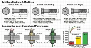
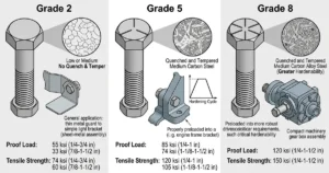
The documents that assign strength grades do not all treat a U-bolt the same way, and the difference matters at the point of order. ISO 898-1 specifies mechanical properties for carbon and alloy steel bolts, screws and studs by property class, and ASTM A307 covers carbon steel bolts, studs and threaded rod in two live grades: Grade A, with a minimum tensile strength of 60 ksi and intended for general applications, and Grade B, with a tensile strength of 60 to 100 ksi and intended for flanged joints in piping systems with cast iron flanges. Grade C is no longer a current grade — it was replaced by Specification F1554 Grade 36. Both ISO 898-1 and A307 are written for straight products, so a class or grade number from either is a requirement to be agreed and verified on the finished bent part rather than an automatic property of it.
SAE J429 is different in kind, and the difference is worth stating precisely. Its scope covers inch-series steel bolts, screws, studs and U-bolts in sizes to 1-1/2 in, and for specification purposes the standard treats U-bolts as studs — so a U-bolt inside that scope is a product the grade requirements are written to apply to, and the question is whether the supplied part meets them. The same standard supplies the caution that belongs under any U-bolt strength figure: the “U” configuration may not sustain a load equivalent to two bolts or studs of the same size and grade, so the actual load-carrying capacity of a U-bolt should be determined by saddle load tests. A grade describes the product. It still does not describe the rated working capacity of the installed assembly, which comes from the design basis for the position — the support configuration, the saddle or contact condition, the load direction, temperature, corrosion allowance, and the factor of safety the governing document applies.
Where a standard does address the formed part, it does so by controlling the sequence. In ASTM A193, the final tempering of Grade B7M has to be carried out after all machining and forming operations, including thread rolling and cutting, so that the properties belong to the finished product rather than to the bar before forming. Apply that principle to any U-bolt carrying a strength claim: the steel, the forming and the heat treatment are one specification, and a certificate for the bar does not by itself describe the bent part.
DIN 3570, the dimension standard that metric pipe U-bolts are commonly ordered to, shows the same split. The DIN 3570 record is dated October 1968, and the standard fixes the sizes, the pipe each size suits and the thread on the legs. It also names a material from its own era — USt 37-1 to DIN 17100, with nuts to strength class 5 of DIN 267 Part 4 — but it carries no working load for the bolt, and today’s stainless, structural and property-class grades sit outside that material clause. A U-bolt bought as “DIN 3570” has a defined shape and a defined historical material; it does not have a rated strength.
What actually limits a U-bolt’s capacity
The material grade sets a ceiling. Four other things decide how far below that ceiling the real capacity sits.
The threaded section, not the nominal diameter
Tensile capacity follows the area of the smallest loaded cross-section, and on a U-bolt that section is normally the thread. The difference is easy to see on standard sizes. In the DIN 3570 table, the U-bolt size that carries M10 legs has a tabulated shank diameter of 8.9 mm — smaller than the thread it carries. The tensile stress area of an M10 × 1.5 thread is about 58 mm², while an 8.9 mm shank measures about 62 mm². The threaded section therefore carries roughly 93% of the shank area, so the leg’s cross-section is close to constant from the bend to the nut.
That is the geometry of a rolled thread formed from a reduced-diameter blank rather than a thread cut into full-diameter bar, and the standard’s table is consistent with it across its size range. Take the other route — turning an M10 thread on 10 mm bar — and the same leg has a 10 mm shank of about 78.5 mm² behind a thread of about 58 mm², roughly 74%. The thread dimension is identical; the section behind it is not. Whether the legs are roll-threaded from a reduced blank or cut from full-diameter bar is worth confirming on the order, along with the thread length, because it decides how much plain shank is left for the support thickness and where the thread sits in the joint.
Thread length and thread position do the same work in the other direction: they decide where along the leg the load is carried and how much plain shank is left for the support thickness. The dimensional side of this — inside width, leg length, thread length and leg centres — is set out in the DIN 3570 U-bolt size chart.
The bend
The bend is the part of a U-bolt that no property-class table describes. Forming puts cold work into the material, the cross-section around the bend is not uniform, and the load path turns through 180°. A property class established on a straight test piece does not automatically represent the behaviour of that region.
Two practical consequences follow. First, the bend has to match what it goes around. A bend that seats on the pipe or plate over a full contact length spreads the load; one that touches at a single point concentrates it and lets the assembly rock, and a U-bolt forced open or closed on site to make it fit is no longer in the condition its properties were established in. Second, load direction matters. A U-bolt is built to take tension along its two legs; when the load arrives across the bend instead — a line pulling sideways out of the clamp, a bracket twisting under a moving load — the legs see bending as well as tension, and a figure derived from tensile capacity no longer describes the condition. Where a position has to resist that kind of loading, it is a requirement for the drawing, not something to be recovered from a bolt grade.
The nuts and the engaged thread
The joint is the bolt plus the nut, and the nut is part of the specification rather than an accessory. A nut of a lower property class than the bolt, or one that leaves threads uncovered, becomes the weakest element in the joint whatever the bolt’s grade says. Where the bolt is specified to ASTM A193, the matching nut specification is ASTM A194/A194M, and the grades are paired rather than interchangeable. Metric property classes work the same way: a bolt class is matched to a nut class, and a U-bolt quoted with a bolt grade and an unspecified nut is only half specified.
Thread engagement is the other half of that relationship. The legs are the part of a U-bolt whose length and thread length are fixed at order, and the arrangement of nuts above and below the support decides how much of the leg is engaged and how the clamping load is applied. That belongs with the support drawing and the installation method, which is covered in the pipe-support U-bolt installation guide.
The support, the holes and the clamped component
The load path continues past the bolt. Oversized or slotted holes, a thin support web, a bracket that deforms under the nut, a thin-wall or non-metallic pipe, and a liner that compresses as the assembly is tightened all change where the load ends up. A U-bolt can be the strongest element in an arrangement that still does not hold anything, and the failure will not look like a bolt failure.
What the U-bolt is doing in the assembly also decides what load reaches it. As a restraint the assembly grips the pipe and carries the working load; as a guide with a specified clearance, the U-bolt holds the pipe in line and carries little or none of its weight, so its strength is not the design question at all. The guide to choosing a U-bolt for pipe support sets out that selection layer.
Grade labels do not transfer between standards
Grade and class designations look comparable on a quotation and are not. Each belongs to the document that defines it, with its own product scope, test methods, size ranges and hardness limits.
| Label you may see | Document behind it | What the label actually covers | What to check |
|---|---|---|---|
| 4.8, 8.8, 10.9, 12.9 | ISO 898-1 property classes | Mechanical properties of carbon and alloy steel bolts, screws and studs with metric thread; the class encodes the nominal tensile strength and the yield ratio, and the values are established by test at ambient temperature | Whether the class is being claimed for the bent U-bolt itself, and how the requirement will be verified on the finished part |
| Grades 1, 2, 4, 5, 8 | SAE J429, Mechanical and Material Requirements for Externally Threaded Fasteners | Inch-series steel bolts, screws, studs and U-bolts in sizes to 1-1/2 in; for specification purposes the standard treats U-bolts as studs, so its mechanical requirements are written to apply to a U-bolt inside that scope | Whether the grade is being claimed for a product inside the standard’s scope, and how it is evidenced on the supplied U-bolt. Grade identification marking is a separate requirement from the mechanical properties — the marking clauses do not apply to studs or to products without a head, so an unmarked U-bolt is not evidence that the grade does not apply. A capacity figure is not the sum of the two legs either: the standard directs that actual load-carrying capacity be determined by saddle load tests |
| B7, B7M, B8, B8M | ASTM A193/A193M, alloy and stainless bolting | Bolting for high-temperature, high-pressure and special-purpose service, with specified strength and hardness requirements; Grade B7M is the lower-hardness variant used where hardness has to be controlled | The matching nut grade to ASTM A194, the hardness testing required, and the heat treatment carried out after forming |
| A2-70, A4-70, A4-80 | ISO 3506-1 | Property classes for corrosion-resistant stainless steel bolts, screws and studs, by grade and condition | Both the grade and the condition, and the fact that corrosion resistance is not a strength claim |
| A307 Grade A, A307 Grade B | ASTM A307 | Carbon steel bolts, studs and threaded rod in two current grades: Grade A at a minimum tensile strength of 60 ksi for general applications, and Grade B at 60 to 100 ksi for flanged joints in piping systems with cast iron flanges. Grade C was replaced by Specification F1554 Grade 36. A low-carbon family, not a high-strength one | Which grade is being quoted — “60 000 psi” describes Grade A only and does not cover Grade B — and whether the requirement is being placed on the rod or bar rather than on the finished bent product |
Three rules keep the labels honest. First, a designation means what its own document says and nothing more, so numbers from different systems cannot be ranked against each other without going back to those documents. Second, higher strength is not automatically better for a U-bolt: at the upper end of the property classes the coating decision becomes a process-control decision, because high-strength steel is the material most at risk from hydrogen introduced during plating — the material and finish question is treated in U-bolt materials and finishes. Third, where a class or grade is claimed for a bent part, agree how it will be verified — a test on the finished U-bolt, a hardness check, or a lot-based certificate — and put that agreement in the order.
How to read a published U-bolt load rating
Load tables for U-bolts and pipe clamps are useful, but only as far as their basis is stated. A figure becomes usable when you can answer all of the following.
- Break load, proof load or working load? A break load describes failure, a proof load describes a test with no permanent set, and a working load is what the position may be used for once a factor of safety has been applied. The three are not interchangeable, and a capacity figure that does not say which one it is cannot be interpreted.
- What is being rated? The bolt alone, the U-bolt with its nuts and plate, or the complete support assembly. A rating can be limited by the pipe, the liner or the structure rather than by the steel.
- Under what conditions? Static or dynamic, the temperature range, the corrosion allowance, the support spacing, and whether the rating assumes a full saddle, a shoe or a liner spreading the contact load.
- Which document, and which factor of safety? A rating is produced by dividing a tested or calculated value by a factor defined in a code, a project specification or a manufacturer’s design basis. If the basis is not stated, the number cannot be checked.
- Tested or calculated — and on what? The finished bent part, or the bar it was made from. The two are not the same evidence for a formed product.
- Per leg or per assembly? These are different quantities, and the gap between them is not simply the leg count. A two-leg U-bolt cannot be assumed to carry twice a per-leg figure, because the U configuration, the bend, the saddle or contact condition and the way the load is actually shared between the two legs all intervene. Use an assembly rating derived from a per-leg value only where the applicable test or design basis supports that load distribution and that assembly value.
- What is the size and bend range? Ratings are established for particular sizes, threads, bends and materials. They do not scale by diameter, and they do not carry across to a different bend form or a different grade.
When a quotation gives a capacity without any of that, the next step is not to accept it or to guess at a margin. It is to ask for the basis, and to keep asking until the answer names the document, the factor and the test or calculation behind the number.
Service conditions that take capacity off the number
Corrosion. Capacity is quoted for a section size, and corrosion removes section. The exposure also decides whether the U-bolt is part of a galvanic couple with the pipe or structure it touches, and whether a coating or a liner is doing work that the base metal cannot do alone.
Temperature. Property classes are established by tests at ambient temperature — ISO 898-1 gives the range for its tests as 10 °C to 35 °C — so a room-temperature figure is not a service-temperature promise. At low temperature, toughness is the concern, and separate bolting specifications exist for it: ASTM A320/A320M for low-temperature service, alongside ASTM A193 for high temperature. At elevated temperature, allowable stress values fall, and the applicable code’s allowable-stress table defines how far a given material may be used. That limit belongs to the table, not to the bolt’s grade name.
Fatigue and vibration. A margin calculated against a static load says nothing about a load that repeats. Under cyclic loading the decisive detail is not the average stress in the rod but the local condition at the thread root and through the bend — which is exactly what a property-class table does not describe. Vibration also loosens joints, so the locking arrangement at the support is part of whether the assembly keeps the capacity it started with.
Tightening and re-use. The tightening value belongs to the joint and comes from the drawing or the assembly documentation, not from a generic torque table. Over-tightening can pre-load a U-bolt close to its limit, damage the coating or the thread, and deform the clamped component. A U-bolt that has been tightened, removed and re-formed has been changed, and whether it may be re-used is a specification question rather than an assumption.
What to put on the enquiry
An order that can actually be verified carries six things:
- The size and the standard — inside width, leg length, thread length, thread size and pitch, and the standard the part is ordered to.
- The strength requirement and the document behind it — a property class, a material grade, or both, with a statement of how the requirement is verified on the finished bent part.
- The finish — and the thread fit that has to go with it, since a coated thread and its nuts are one decision.
- The load the position must carry and the factor of safety the project requires — taken from the drawing, the support specification or the project documents.
- The nuts — class or grade matched to the bolt, quantity, and whether washers or plates are included.
- The documentation required — mill certificate, test report, hardness testing, and whether the test is on the finished part or on the material it was made from.
None of this replaces the engineering calculation for the position. Its purpose is to give that calculation something to be checked against: a U-bolt ordered with a grade but no finish, or with a capacity but no basis, cannot be verified when it arrives, and the point at which that becomes visible is usually the point at which correcting it is expensive.
ChinaBolts supplies DIN 3570 U-bolts in carbon and stainless steel, in Form A and Form B, with matching nuts and washers, as part of a wider bolts range. Send the size and thread, the material or property class and finish, and the load or specification the position has to meet, and the requirement can be confirmed before the order is placed.