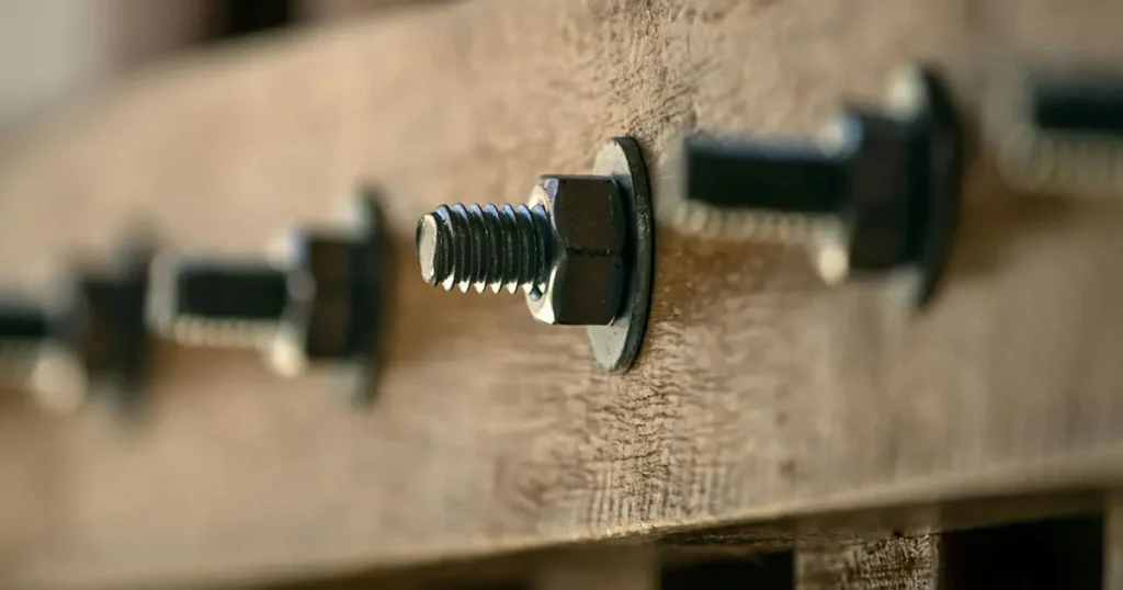
Carriage bolts, elevator bolts and step bolts are close relatives. All three have a low-profile circular head, no wrenching flats, and a feature under the head that stops the bolt turning while the nut is run up. Almost everything that matters when you choose between them happens at that head. In ASME B18.5, Round Head Bolts (Inch Series), the standard that dimensions all three in inch sizes, each is a separate product type with its own clause and its own dimensional table, and the tables describe three different heads on three different under-head arrangements.
The short version, by head shape. A carriage bolt has a domed head on a flat bearing surface. An elevator bolt has a much wider, comparatively flat head with a shallow conical bearing surface that seats into a recess. A step bolt also has a much wider head than a carriage bolt, but keeps a low rounded top and a flat bearing surface, because that head is what someone stands on. Same thread, same nut, same standard family, three different parts.
The three types inside ASME B18.5
ASME B18.5-2012 (R2023) is the edition in effect, and ASME has placed the standard on stabilized maintenance. Its scope is the general and dimensional data for the inch-series bolts classified as round head bolts, and clause 1.2 defines the types one by one. Three of them are the subject of this comparison:
- Round head square neck bolt (clause 1.2.2, Table 2). The type known in the trade as a carriage bolt: a circular head with a low rounded top and a flat bearing surface, and an integrally formed square neck under the head.
- Step bolt (clause 1.2.6, Table 6). Defined as a large circular head with a low rounded top surface and a flat bearing surface, and an integrally formed square neck under the head.
- Flat countersunk head elevator bolt (clause 1.2.9, Table 9). Defined as a large circular head with a flat top surface and a shallow conical bearing surface, and an integrally formed square neck under the head.
A fourth type explains most of the confusion in the market. The round head fin neck bolt (clause 1.2.5, Table 5), formerly the fin neck carriage bolt, keeps the carriage-bolt head but replaces the square neck with two diametrically opposite fins at the junction of head and shank. ASME does not call it an elevator bolt, yet it is sold under similar language in some catalogues, and it is not a substitute for either of the two designs above. On a quotation, the under-head feature identifies the part more reliably than the product name does.
One point applies to all four types. ASME B18.5 fixes form and dimensions; it does not fix strength. The thread is specified as Unified coarse (UNC or UNRC), Class 2A, uncoated, and material and mechanical properties are referred out to ASTM A307, ASTM F468, ASTM F593 and SAE J429, with surface discontinuities to ASTM F788/F788M. An order that says only “ASME B18.5” has therefore defined a shape, not a grade.
The shape is what the catalogue line describes. ChinaBolts lists the inch-series ASME B18.5 round head square neck bolts from #10 to 1 in.
Head profile: three different jobs for one low-profile idea
Carriage bolt: domed head, flat bearing surface
The carriage bolt head is circular with a low rounded top and a flat underside that bears directly on the material. No recess is needed, because the head simply sits on the face. The absence of corners is why it turns up on trailer decks, dock boards, benches, fencing and playground equipment. What it cannot do is disappear. The dome protrudes by its full head height, so anything sliding across the joint meets a bump, and the head carries no drive feature at all: the bolt can only be turned by the nut.
Elevator bolt: a wide, almost flat head with a shallow conical seat
The flat countersunk head elevator bolt is the type ASME actually names “elevator”. Its head is wide and comparatively flat, and its bearing surface is a shallow cone rather than a flat face. That cone is the design: it seats into a matching countersink or formed recess, and the wide head spreads clamp load across a thin panel instead of punching through it. ASME describes elevator bolts as of similar design to round head bolts “but with a comparatively flat head frequently used in agricultural applications such as grain and other such elevators”, which is where the name comes from. A domed carriage bolt head in the same position would stand proud of the bucket wall, could catch on the product stream, and would bear on a much smaller area.
Step bolt: a wide head meant to be stepped on
ASME describes step bolts as “of similar design to a round head, square-necked bolt but with a much larger head size”. The head height stays the same as a carriage bolt at each size; it is the diameter that grows. The top remains low-domed and the underside flat, so a step bolt needs a flat face rather than a countersink, and its head works as a small platform, spreading a foot load instead of giving the sole a point to slide off.
How large that platform has to be is set by access rules rather than by the fastener standard. California’s telecommunications safety orders, for example, require permanent steps on poles and towers to be at least 5/8 in in diameter, to provide a minimum clear tread width of 4 1/2 in, to be spaced no more than 18 in apart, and to place the lowest permanent step at least 7 ft 6 in above the ground line (Cal. Code Regs. Tit. 8, § 8608). Those figures sit well outside the ASME B18.5 step-bolt table, which runs from No. 10 to 1/2 in nominal diameter and reaches a maximum head diameter of 1.594 in at 1/2 in. A pole step of the regulated kind is a drawing item, not a catalogue step bolt, and the two are not interchangeable even though both are called step bolts.
Head size in the tables: what “large” actually means
The tables make the difference measurable. At 1/2 in nominal diameter, the largest size that all four types share, the heads compare as follows. All dimensions are in inches, maximum/minimum.
| Feature (1/2 in nominal) | Round head square neck (Table 2) | Flat countersunk head elevator (Table 9) | Step bolt (Table 6) | Round head fin neck (Table 5) |
|---|---|---|---|---|
| Head diameter | 1.094 / 1.032 | 1.602 / 1.562 | 1.594 / 1.563 | 1.094 / 1.032 |
| Head height | 0.270 / 0.250 | 0.176 / 0.156 | 0.270 / 0.250 | 0.270 / 0.250 |
| Bearing surface | Flat | Shallow conical | Flat | Flat |
| Under-head feature | Square neck | Square neck | Square neck | Two fins |
| Width across neck or fins | 0.515 / 0.492 | 0.530 / 0.492 | 0.515 / 0.492 | 0.833 / 0.813 |
| Depth of neck or fins | 0.281 / 0.250 | 0.281 / 0.250 | 0.281 / 0.250 | 0.198 / 0.188 |
| Nominal length measured to | Bearing surface | Top of head | Bearing surface | Bearing surface |
Head diameter relative to bolt diameter at that size is about 2.2:1 on the carriage bolt and about 3.2:1 on both the elevator and the step bolt. At No. 10 the spread is wider still: 0.469 in on a carriage bolt, 0.790 in on the elevator bolt and 0.656 in on the step bolt, against a 0.190 in nominal diameter.
Read the table again for what it says about identification. At 1/2 in the elevator and step bolt heads are almost the same diameter, 1.602 and 1.594 in, and they are different parts in every other respect: 0.176 in head height against 0.270 in, conical against flat bearing surface, length measured to the top of the head against length measured to the bearing surface. A head diameter measured across the top will not tell you which one you have. Head height and the underside will.
Figures here are quoted from the ASME B18.5 dimensional tables. Where a drawing or order names a particular edition, check the values against that edition rather than against this summary.
Under-head geometry: what the hole has to provide
Carriage, elevator and step bolts all use the square neck, and at 1/2 in the three tables give it almost identical limits: 0.515 to 0.492 in across the flats and 0.281 to 0.250 in deep, with the elevator type allowed up to 0.530 in across. The neck is the common feature, not the distinguishing one. A square opening cut for one will usually accept the others, and that similarity is exactly why the head gets overlooked.
The neck still has to be engaged. It is 0.250 to 0.281 in deep, so material thinner than that at the head face cannot swallow it; in that case the joint needs a punched or broached square opening, and if the opening is round the bolt has nothing to resist rotation. A carriage bolt in a round clearance hole is a bolt that turns with the nut and never develops tension. The same is true of a step bolt.
The fin neck bolt uses a different arrangement altogether: two fins, 0.833 to 0.813 in across at 1/2 in, which is about 1.67 times the bolt diameter, 0.208 to 0.188 in thick and 0.198 to 0.188 in deep. Nothing about that fits a square hole. The fins need a slot, two notches, or a material soft enough to be pressed into, and this is also the shallowest engagement in the group, which matters when the clamped material is thin.
The elevator bolt adds one more requirement. Because its bearing surface is a shallow cone, the face it bears on needs a matching countersink or a formed recess. Without one, the head contacts the surface along its outer edge only, and the load path runs through a ring rather than through the full head area.
Metric versions of the same idea change the neck rather than the head. ISO 8678:1988 covers cup head square neck bolts with a small head and a short neck in product grade B, M6 to M20. Its neck is short by design, so it engages less material than a standard carriage-bolt neck and needs a joint designed for it; the ISO 8678 cup head square neck bolts page sets out the sizes that are actually supplied.
Length and thread: where the ordering traps are
ASME B18.5 measures length parallel to the axis from the end of the bolt to the bearing surface for bolts with flat bearing surface heads, and to the top of the head for bolts with countersunk-type heads (clause 2.4.1). Carriage, step and fin neck bolts all have flat bearing surfaces, so their nominal length stops at the underside of the head. The flat countersunk head elevator bolt does not: its nominal length includes the head itself.
The numbers matter at the counter. At 1/2 in the elevator head is 0.156 to 0.176 in high, so a 1/2-13 × 4 elevator bolt leaves roughly 3.82 to 3.84 in of shank below the head, while a 1/2-13 × 4 carriage or step bolt leaves the full 4 in within the standard’s length tolerance. If the joint needs 4 in of grip under the head, the elevator bolt has to be ordered longer than the carriage bolt it replaced.
Head height and neck depth are measured differently on the countersunk type as well. For a flat bearing surface head, head height runs from the top of the head to the bearing surface, and neck depth from the bottom of the square to the bearing surface (clauses 2.1.1 and 2.2.1). For a countersunk head, both run to the point where the conical bearing surface meets the flat of the square neck. Measuring an elevator bolt with the method used on a carriage bolt produces numbers that do not match the table, and a part that looks out of tolerance when it is not.
Thread is Unified coarse (UNC/UNRC), Class 2A, across these types, and the minimum thread length is twice the basic bolt diameter plus 0.25 in for nominal lengths of 6 in or less (clauses 2.5 and 2.6.2). At 1/2 in that is 1.25 in minimum. The neck is unthreaded, so the unthreaded portion has to reach through the material at the head before the thread starts carrying load.
Why the same standard family does not make them interchangeable
One document, one thread form and one shared square neck make these designs look interchangeable. Six things say otherwise.
- The standard number does not name the part. ASME B18.5 covers ten round head types in separate tables. A purchase order that cites only the standard leaves the type open, and any of the three will fit the same 1/2-13 nut.
- The head needs somewhere to sit. A carriage or step head wants a flat face. An elevator head wants a countersink, and on a flat face it bears on its outer edge only.
- Head diameter is a clearance dimension. A recess cut for a 1.094 in carriage bolt head will not take a 1.594 in step bolt head, and the carriage bolt head spreads its clamp load over less than half the area of either wide-head type at the same diameter.
- The under-head feature decides the hole. A square neck and two fins are not interchangeable preparations, and a fin neck bolt in a square hole has nothing to grip.
- Length is measured on a different basis on the elevator bolt. The same nominal length delivers a shorter grip under the head.
- The head is where the load enters the clamped part. Changing the head changes the bearing stress on the panel, the size of the recess, and the way the bolt resists being pulled through.
Put the other way round: at the same diameter, thread and material specification, all three carry the same thread, and the thread carries the same load. Everything that distinguishes them happens above the thread, which is precisely the region the standard tables spend their columns on.
Choosing between them
Work from what the head has to do, then check that the joint can be prepared for it.
| The joint needs | Design | What to check before ordering |
|---|---|---|
| A smooth, snag-free head on a flat face, with the nut side accessible | Round head square neck bolt (carriage) | Neck depth against material thickness; a square hole, or a material soft enough for the neck to bed into |
| A head that sits at or near flush in a thin panel, bucket wall or belt, with the load spread wide | Flat countersunk head elevator bolt | A countersink or formed recess; the length basis, because the head is inside the nominal length |
| A tread, or a wide bearing pad, on a flat face | Step bolt | Head diameter for the tread width; neck engagement; sizes above 1/2 in need a drawing |
| Two notches or a slot rather than a square hole | Round head fin neck bolt | Fin thickness and fin depth against the slot |
| A round hole and no way to prepare a square or slotted seat | Not one of these | A square-neck bolt in a round hole will turn; use a design with a wrenching feature instead |
When the joint needs something outside the tables, such as a 5/8 in pole step, a head larger than the standard series or a metric elevator head, the part becomes a drawing item. Put the head diameter, head height, bearing surface, neck or fin dimensions, thread and length basis on the drawing and quote it as a special. Other bolt families for the same duties are organised in the bolts category.
Specifying on a purchase order
A line item that can be manufactured without a follow-up question names the type, separates dimensions from properties, and states the finish and the nut. Six items do that:
- Type and table. Round head square neck bolt (Table 2), flat countersunk head elevator bolt (Table 9), step bolt (Table 6), or round head fin neck bolt (Table 5).
- Diameter, thread series and length, with the length basis stated where the part is an elevator bolt.
- Material specification and grade, for example ASTM A307 Grade A, ASTM F593, ASTM F468 or an SAE J429 grade. This is the line that sets strength.
- Finish, such as plain, zinc electroplated to ASTM F1941 or hot-dip galvanized, stated at enquiry so coating thickness and thread fit are handled deliberately.
- The nut, specified and grade-matched to the bolt.
- Head and neck dimensions whenever they are not taken straight from the table.
ASME B18.5 supplies the pattern, and its own designation example is worth copying: “Step bolt ASME B18.5, 1/2-13 × 4, stainless steel, ASTM F 593 alloy group 1.” The same structure applied to the carriage type reads: round head square neck bolt, ASME B18.5, 1/2-13 × 4, steel ASTM A307 Grade A, zinc plated ASTM F1941, Fe/Zn 3A. Both lines name the type inside the standard, so neither can be filled with the wrong head.
Metric buying uses a different document for the same head. DIN 603, Cup head square neck bolts, is the metric carriage-bolt standard, and its current edition is DIN 603:2026-08, which replaced DIN 603:2017-05. The DIN 603 cup head square neck bolts page covers the metric sizes in the same way. ISO 8678:1988, the small-head short-neck version, was confirmed current in August 2025. Neither document defines a step or an elevator head, so those forms in metric threads normally go on a drawing with the head dimensions stated.
Most of these questions are settled by one look at the underside of the head. A flat bearing surface with a domed top and a square neck is a carriage bolt; the same flat underside under a much wider, similarly low head is a step bolt; a shallow cone instead of a flat face is an elevator bolt; two fins are a fin neck bolt. The name on the box is the least reliable part of the identification.